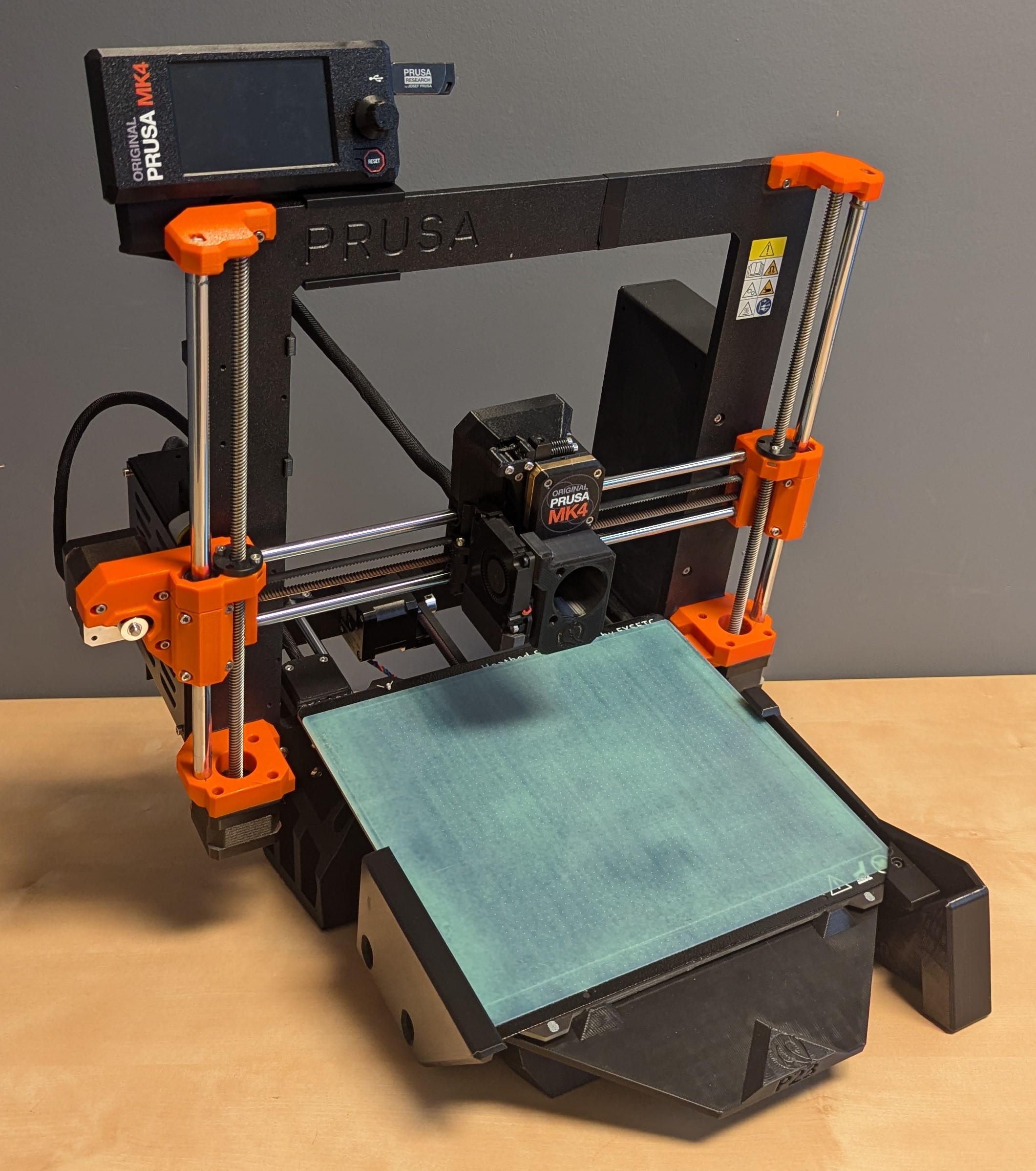
Prusa MK4
-
Update Firmware: Update your firmware to the latest official release as per Prusa's instructions.
-
Plug in USB drive: Ensure USB drive remains plugged in to the LCD screen.
-
Set Printer to Automated Mode: Please follow the instructions here to set your printer to automated mode.
1. What’s in the Kit
Printed Parts
- 1 x Front Brace (P1)
- 2 x Part guidance ramps (P24, P25)
- Inner Ramp Left (P24)
- Inner Ramp Right (P25)
- 1 x LCD mount bracket (P26)
- 2 x LCD wire clips (P22)
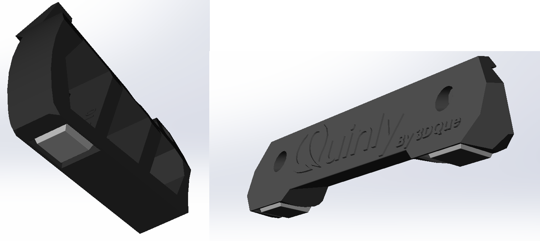
- 1 x Left Tilt Bracket (P10)
- 1 x Right Tilt Bracket (P11)
- 1 x Enclosure Panel Spacer (P28)
- 1 x Hotend Ram (P29)
- 1 x Bed Flexor (P30)
- 1 x Corner Attachment (P31)
- 1 x Bed Guide (P32)
Hardware
- 5 x M5x8 Button head screws
- 2 x M5x12 Button head screws
- 7 x M5 3030 T-nuts
- 1 x M3x8 Cap screw
- 1 x M3x16 Cap screw
- 1 x M3 Hex nut
- 4 x Rubber Feet
2. What You’ll Need
- 2mm Allen key
- 3mm Allen key
- Torx T10 key
- Side cutters
- Needle-nose pliers
3. Install Instructions
3.1 Detach LCD
-
Remove the LCD and spool holder, keep the LCD frame mounting hardware (4 x M3 screws) for later.
-
Remove all cable guiding clips from the bottom printer frame (6 total).
-
Cut zipties from cable guiding clips as well as any zipties securing the LCD cables (ribbon cable and yellow PE cable) to the frame.
-
Carefully reroute the LCD under the frame and out the back-left side of the printer, ensuring neither cable is pinched under the frame.
Needle-nose pliers are a useful tool for removing the cable guiding clips.
3.2 Install Tilt Brackets
1. Adhere Rubber Feet
Adhere rubber feet to the bottom of the tilt brackets (P10/P11) and front brace (P1) if not preinstalled.
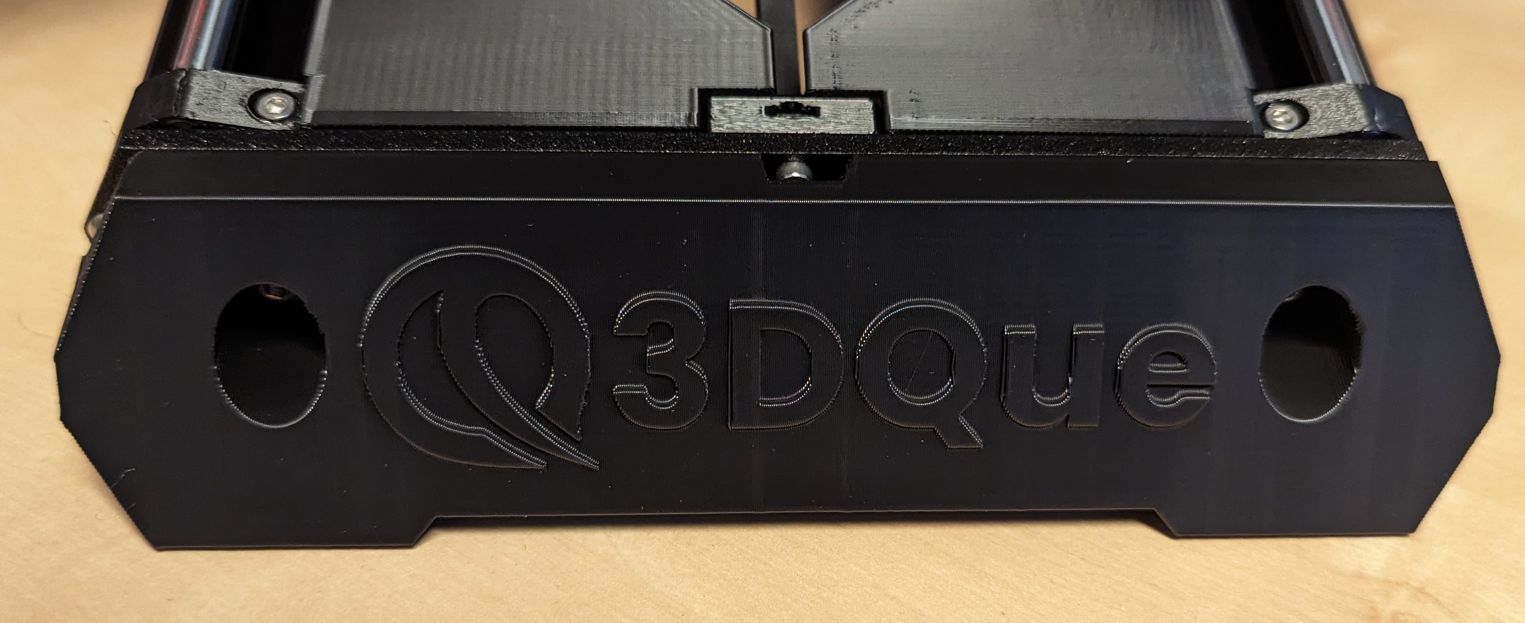
2. Install Front Brace
- Unscrew the screws at the front of the printer (use them in the next step).
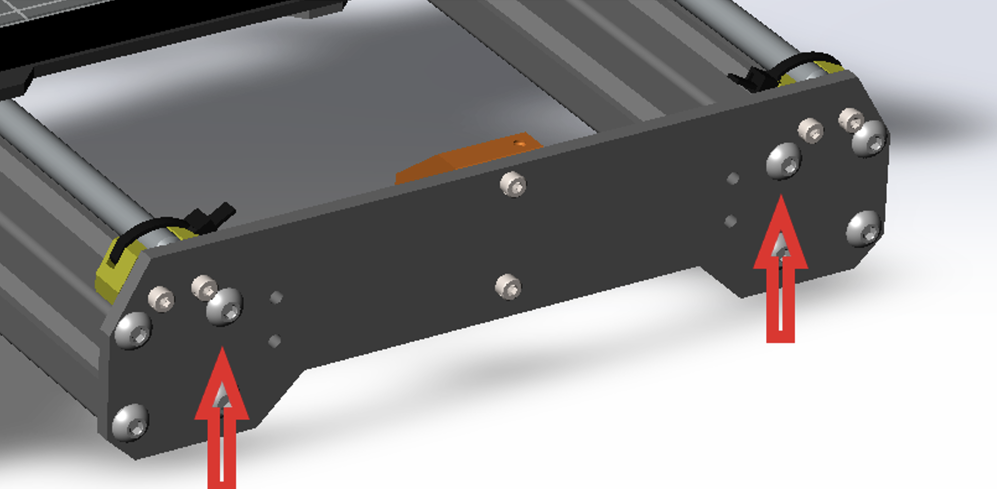
- Install front brace (P1) using the screws from the previous step.
3. Install Tilt Brackets
-
Prepare the tilt brackets (P10/P11) by installing the M5x8mm and 3030 T-nuts.
-
Lay the printer on its right side and complete the following steps with the left tilt bracket (P10).
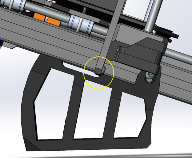
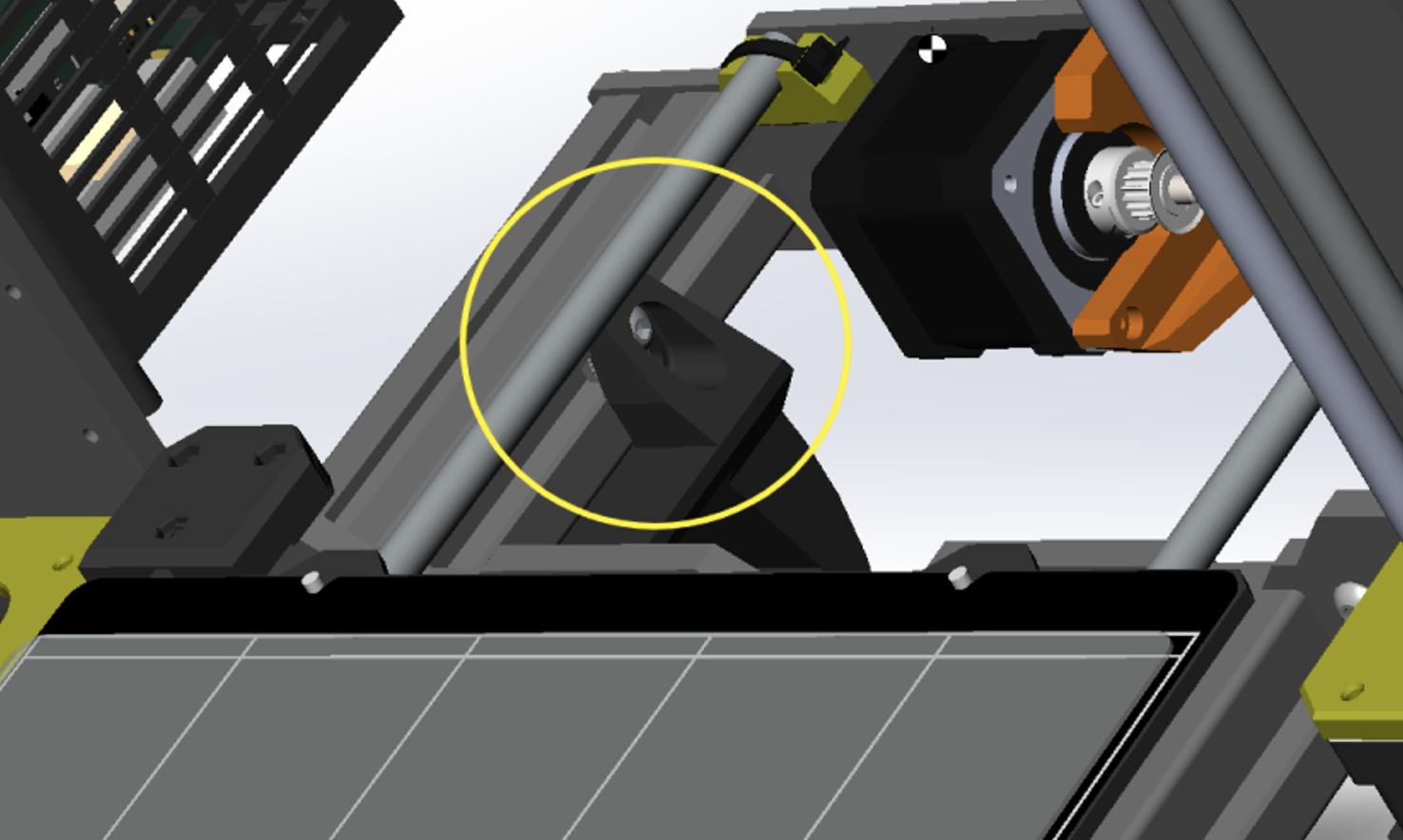
a. Using the left tilt bracket (P10), slide in the front T-nut without tightening it, as shown below.
b. Slide back P10 until the z-frame of the printer sits on the notch of the tilt bracket.
c. Slide the bed forward and slide in the rear bolt/T-nut.
d. Move bed back and tighten front bolt/T-nut.
e. Lay printer on left side and repeat steps with right tilt bracket.
-
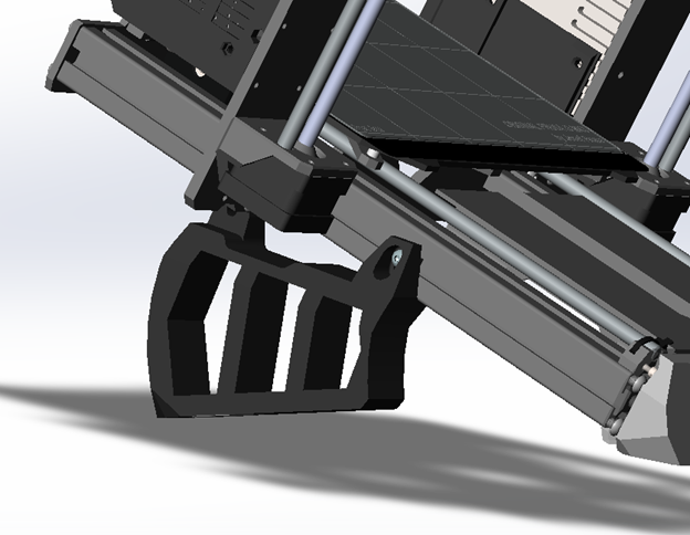
Once both tilt brackets are installed properly, rotate the printer and allow it to stand on the tilt brackets.
-
Clip the inner ramps (P24, P25) onto the inside of the MK4 frame as shown below, ensuring they come flush with the front plate.
3.3 Relocate LCD Screen
- Remove the door panel from the electronics enclosure on the left side of the printer.
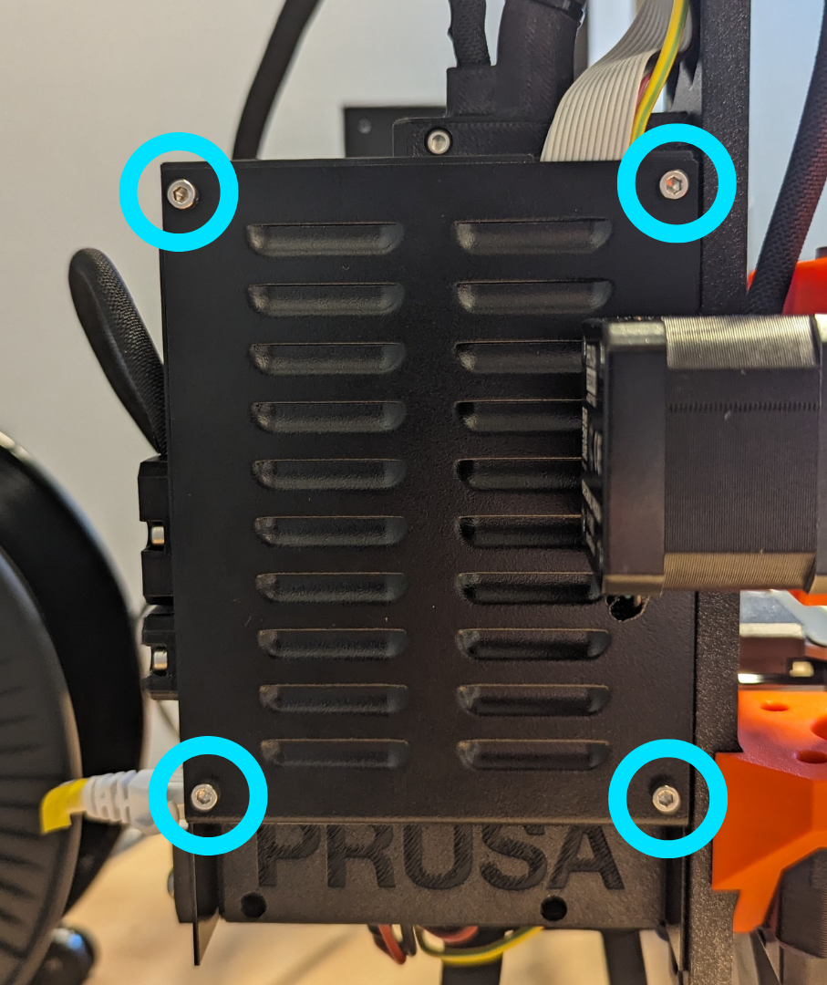
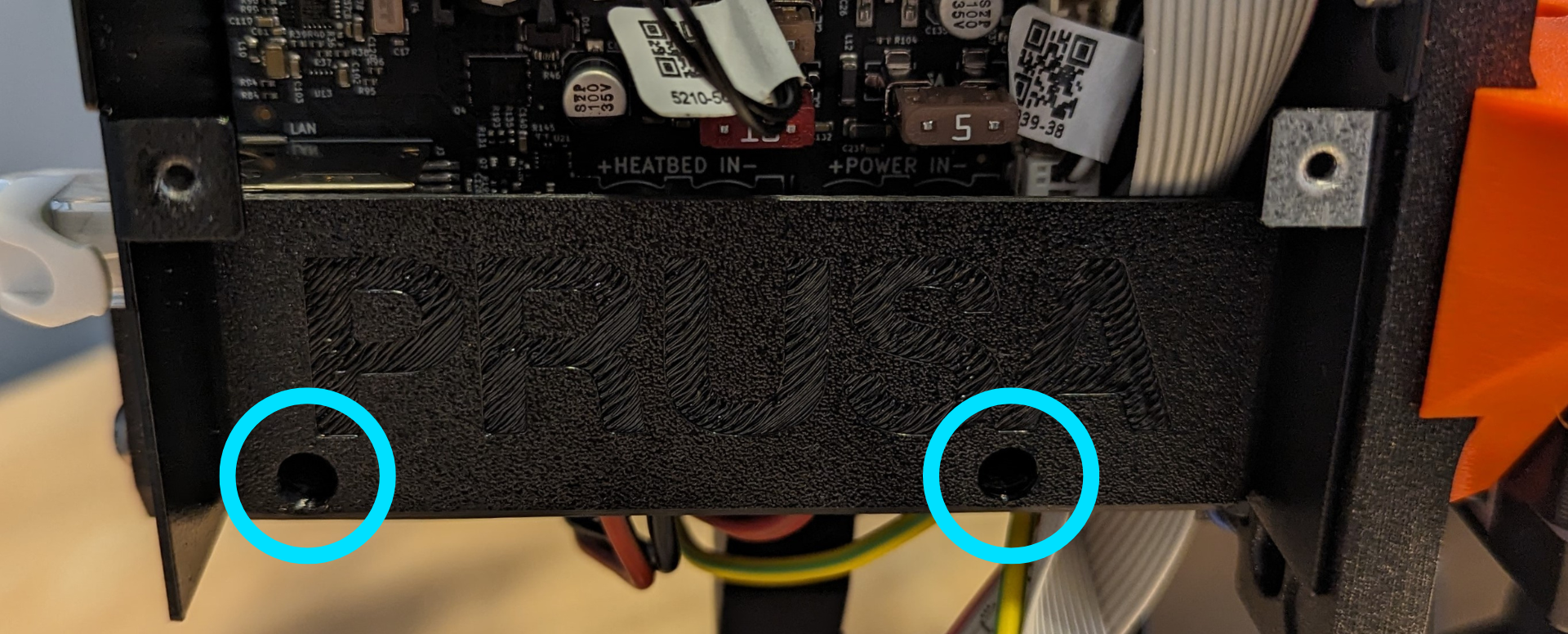
- Unscrew the two screws securing the “PRUSA” cover from the bottom of the enclosure and remove the piece.
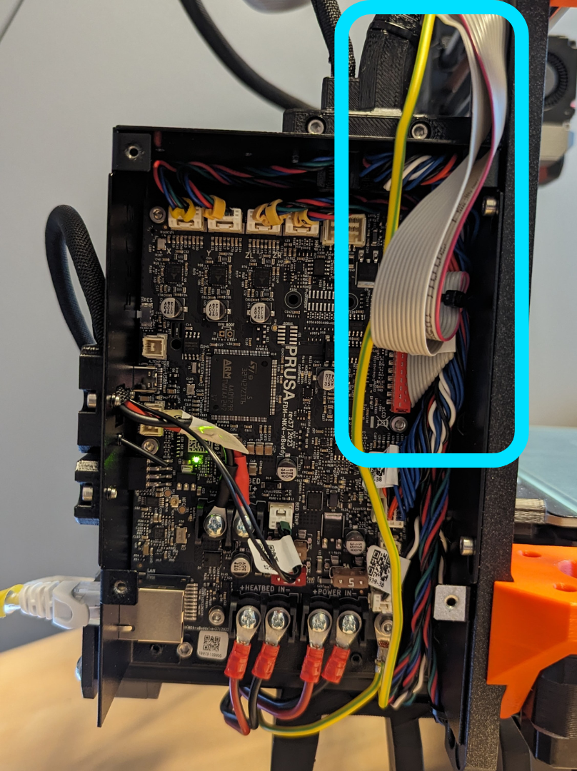
- Cut the 3 zipties securing the LCD cables inside of the enclosure and reroute the LCD cable (ribbon and PE cable) out the top of the enclosure.
-
Replace the “PRUSA” cover inside the enclosure.
-
Using the LCD frame mounting hardware kept from step 1, replace the door panel on the enclosure, adding the enclosure spacer (P28) between the panel and the enclosure.
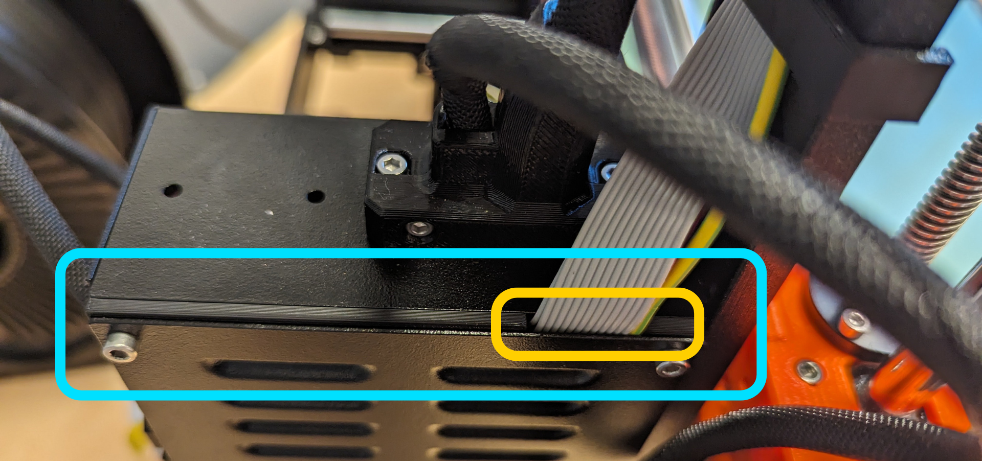
The spacer cutout should be in the top-right corner of the enclosure, allowing the LCD cables to be routed out the top of the enclosure.
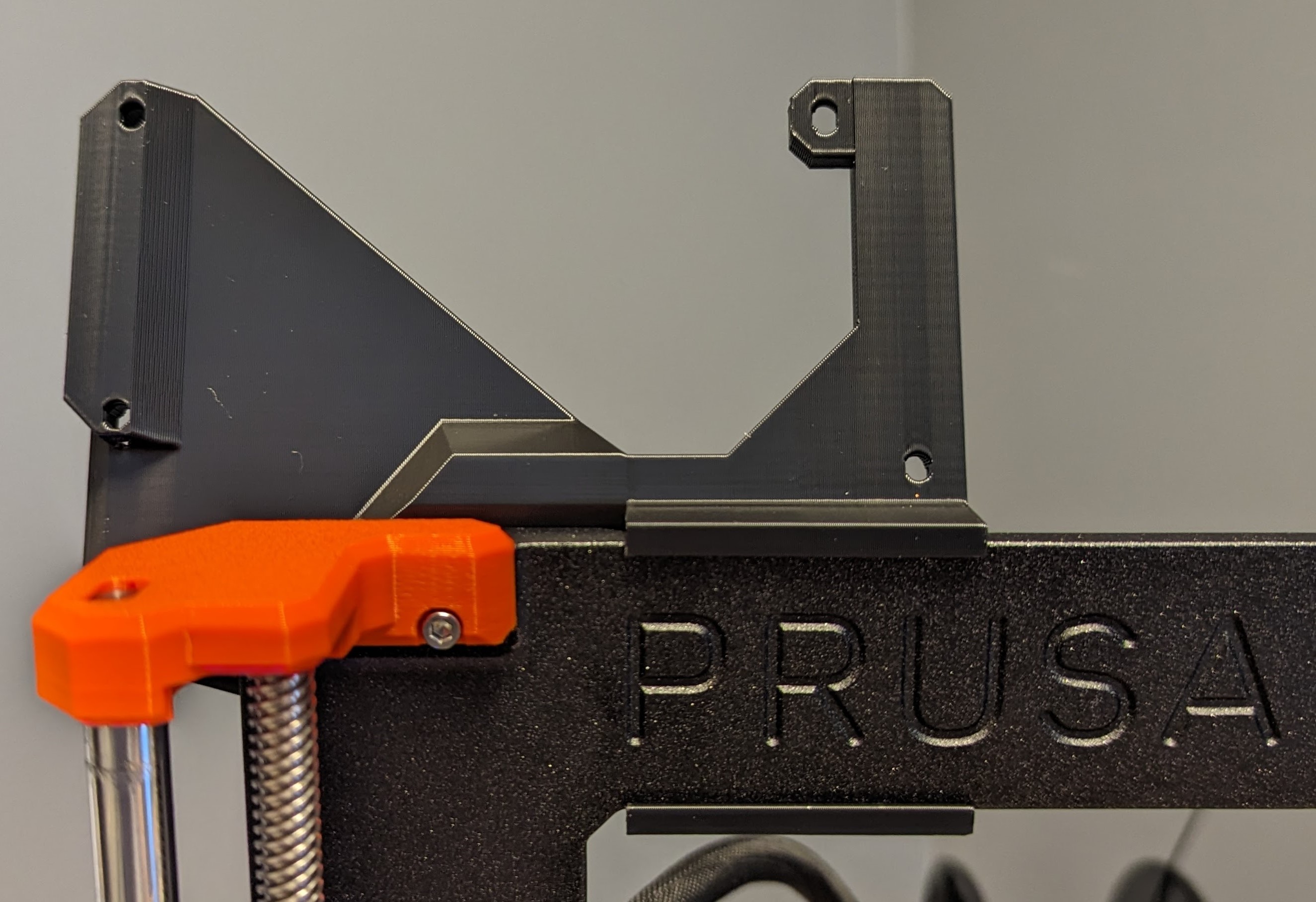
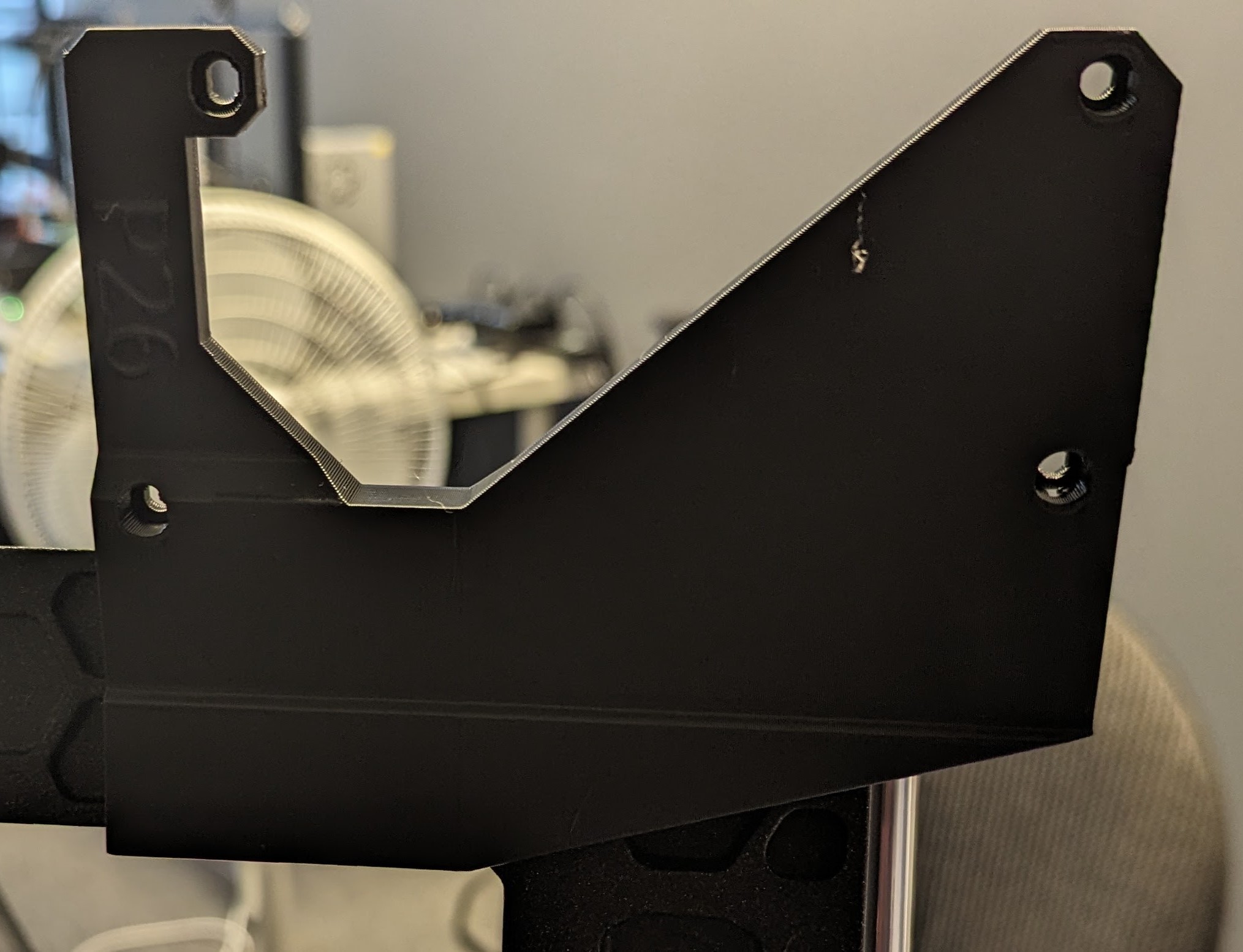
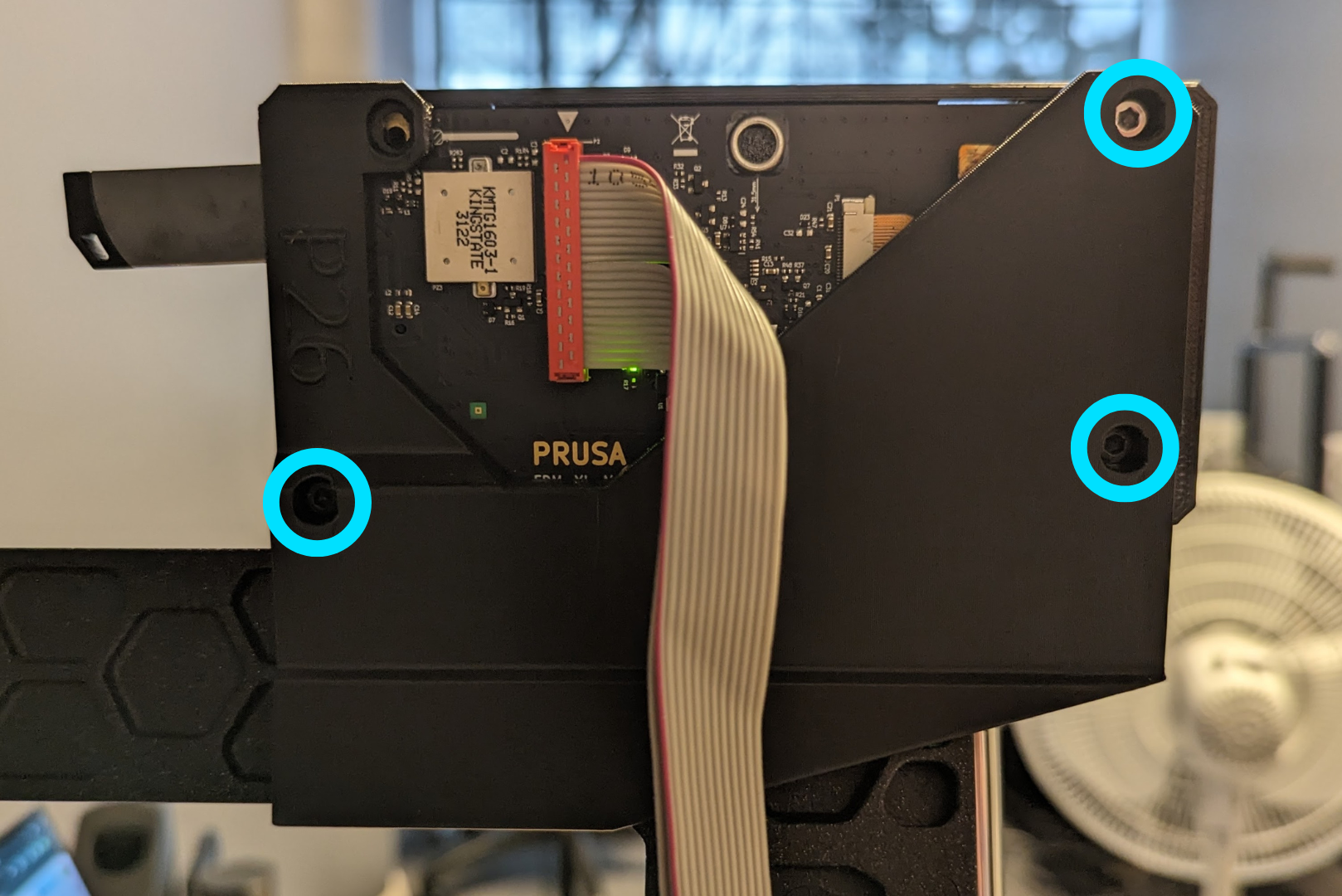
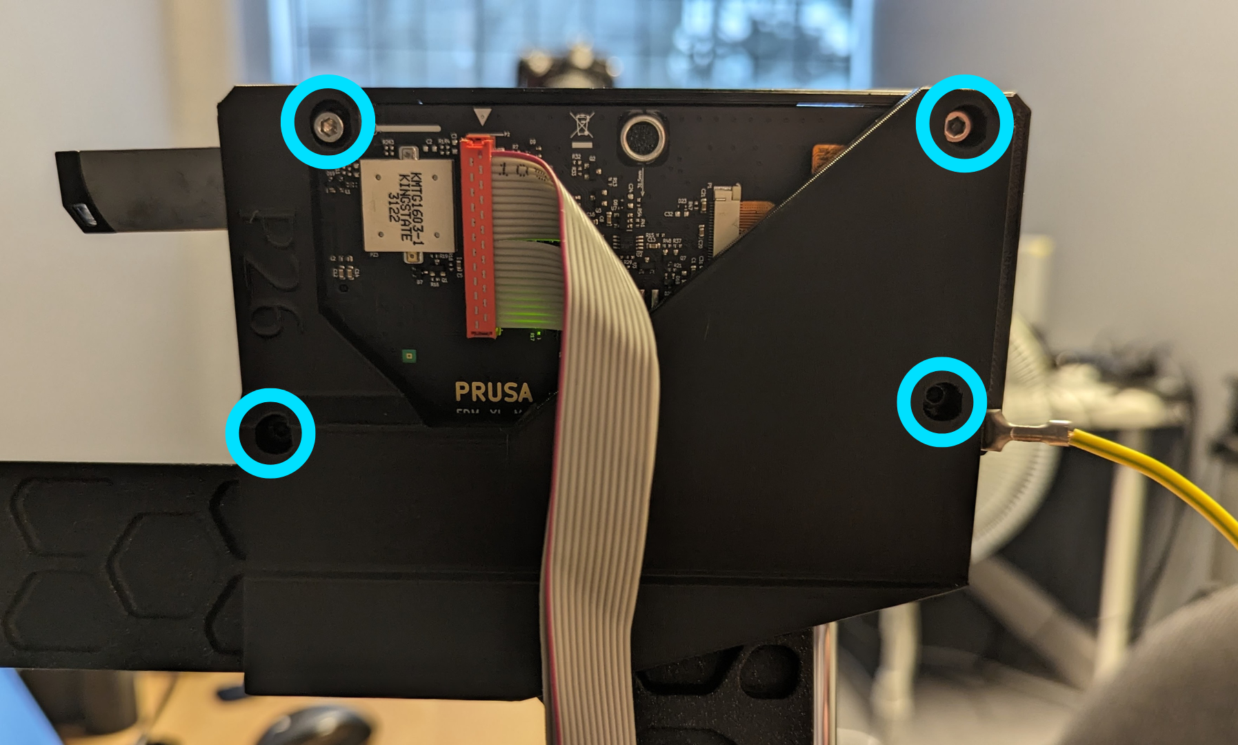
- Clip the LCD mount bracket (P26) to the top of the frame, sliding it as far left as it can go, as shown below.
- There are two slightly different versions of the LCD board. Follow the below instructions for the version you have.
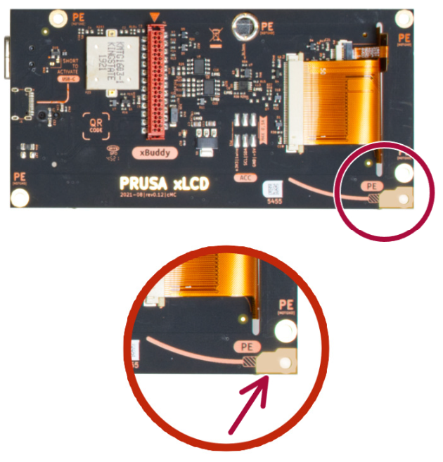
To determine which board you have, find the mounting point for the yellow PE cable on the back of the LCD board.
- Version A of the board has this mount near the top left corner.
- Version B has this mount near the bottom right corner.
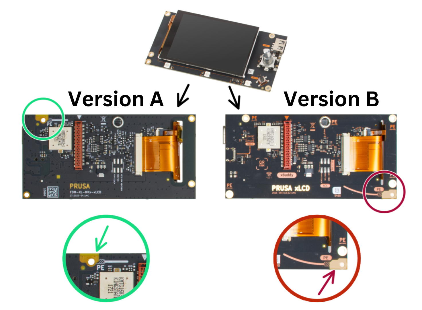
- Version A
- Version B
7.1 Unscrew the four screws on the back of the LCD holding the mount pieces (and yellow PE cable) onto the LCD board, keeping the screws (4x M3x8) for later.
7.2 Push the LCD out of the LCD cover slightly to remove the left mount piece.
You may need to remove the LCD knob and USB stick from the LCD.
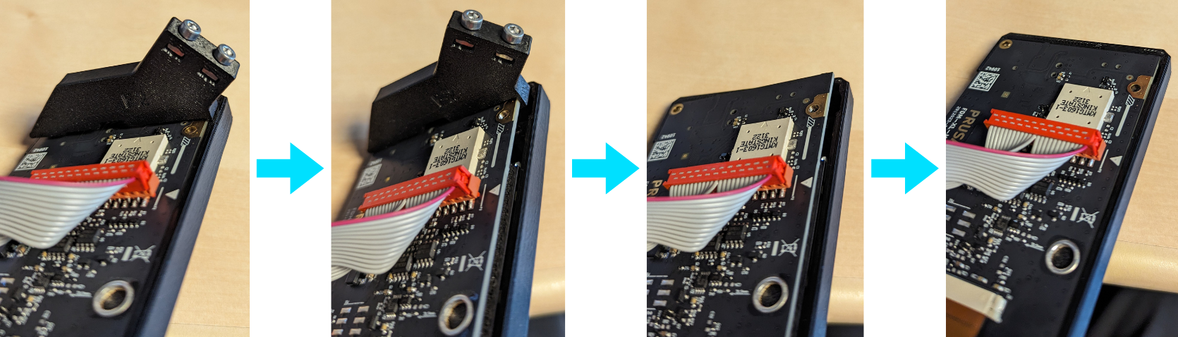
7.3 Push the LCD back into the LCD cover.
7.4 Using three of the M3x8 screws set aside in step 7.1, screw the following three points of the LCD board to the LCD mount bracket (P26).
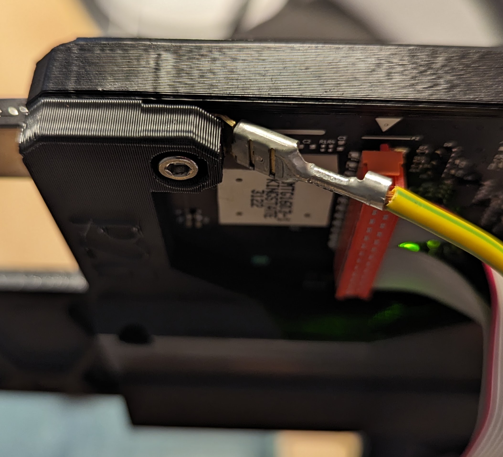
7.5 Slide the end of the yellow PE cable under the top left hole of the LCD mount bracket (P26).
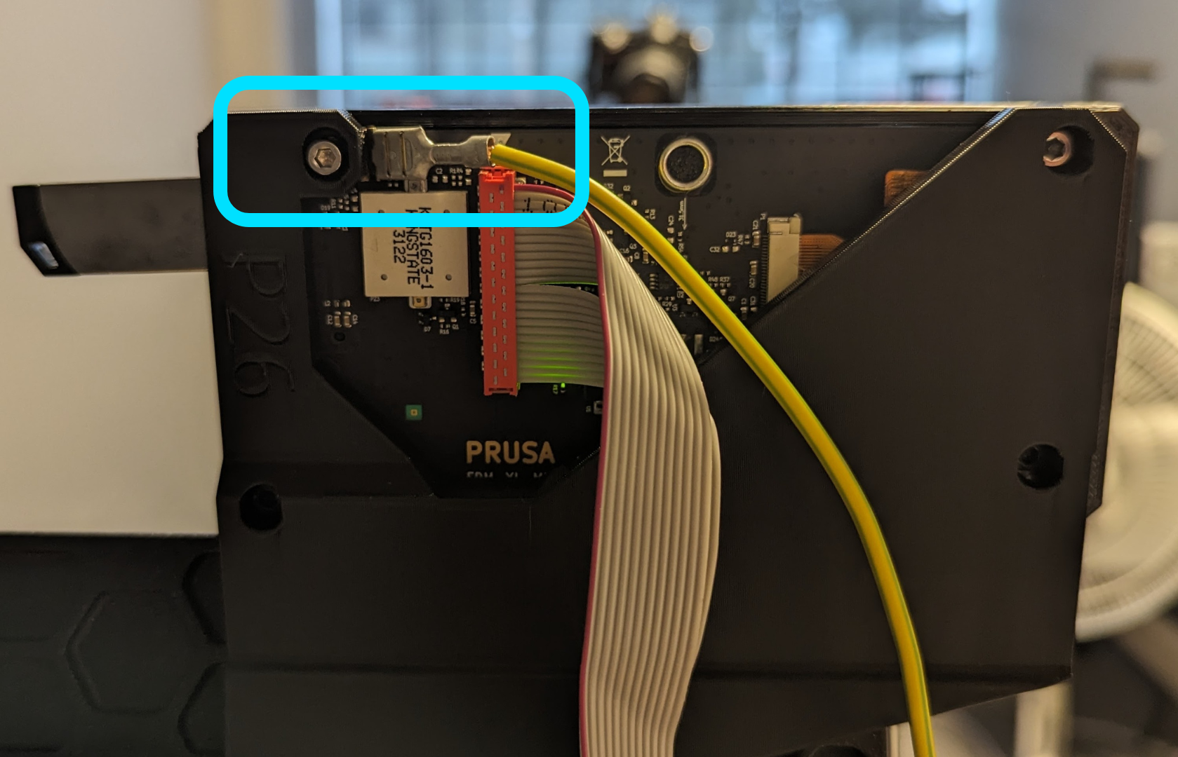
7.6 Using the other screw set aside in step 7.1, screw this last point of the LCD board to the LCD mount bracket (P26), ensuring the yellow PE cable is firmly secured in place.
7.1 Unscrew the five screws on the back of the LCD holding the mount pieces (and yellow PE cable) onto the LCD board, keeping the screws (5x M3x8rT) for later.
7.2 Push the LCD out of the LCD cover slightly to remove the left mount piece.
You may need to remove the LCD knob and USB stick from the LCD.
7.3 Push the LCD back into the LCD cover.
7.4 Using one of the M3x8rT screws set aside in step 7.1, screw the yellow PE cable into its mounting point on the bottom right of the LCD board, ensuring the cable exits out the right side of the board.
Yellow PE cable should be routed in the opposite direction of the graphic shown on LCD board.
7.5 Using the four other screws set aside in step 7.1, screw the following four points of the LCD board to the LCD mount bracket (P26).
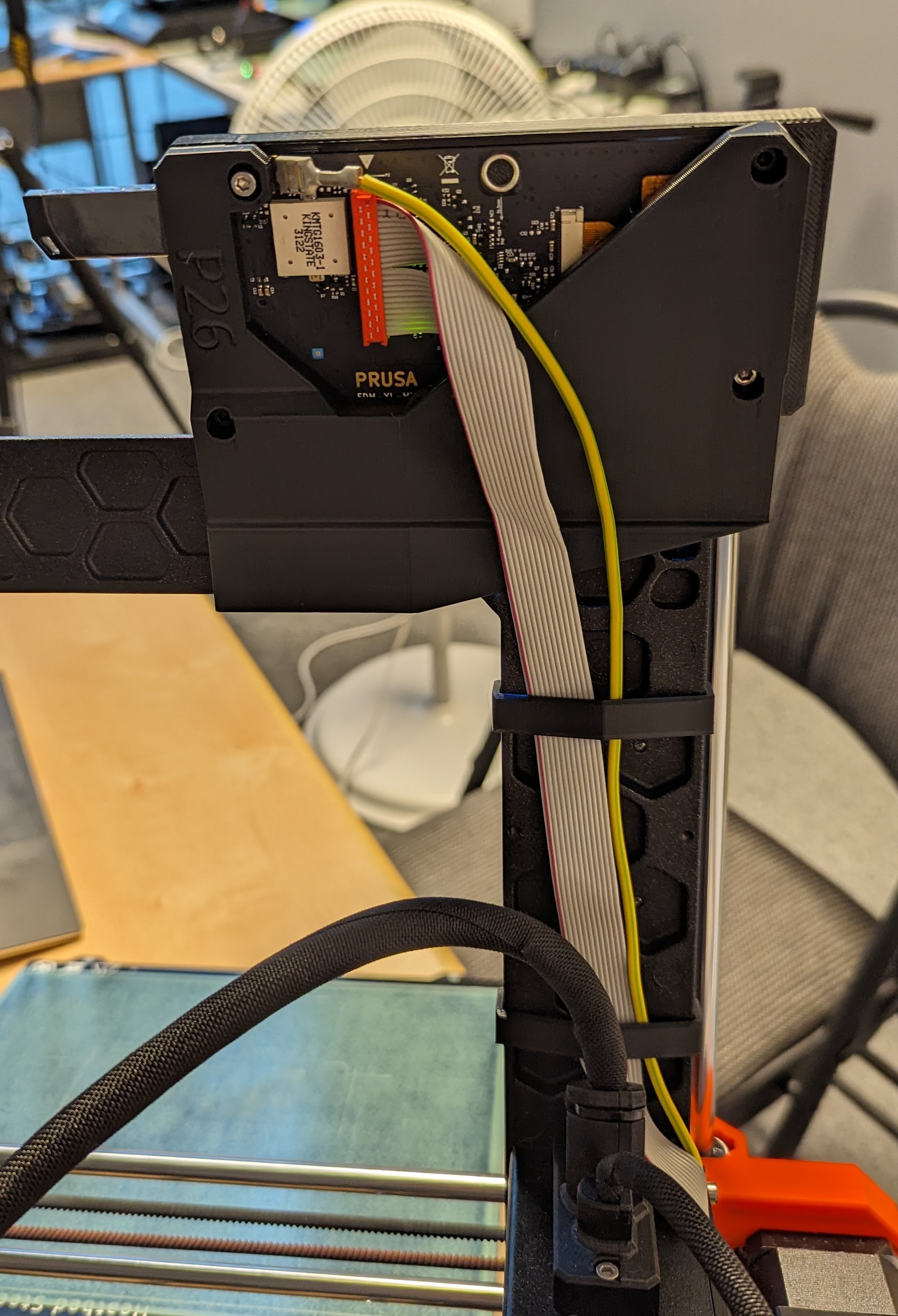
- Route the LCD ribbon cable and yellow PE cable as shown below using the two wire clips (P22) to keep the cables out of the way.
3.4 Install Hotend Guard
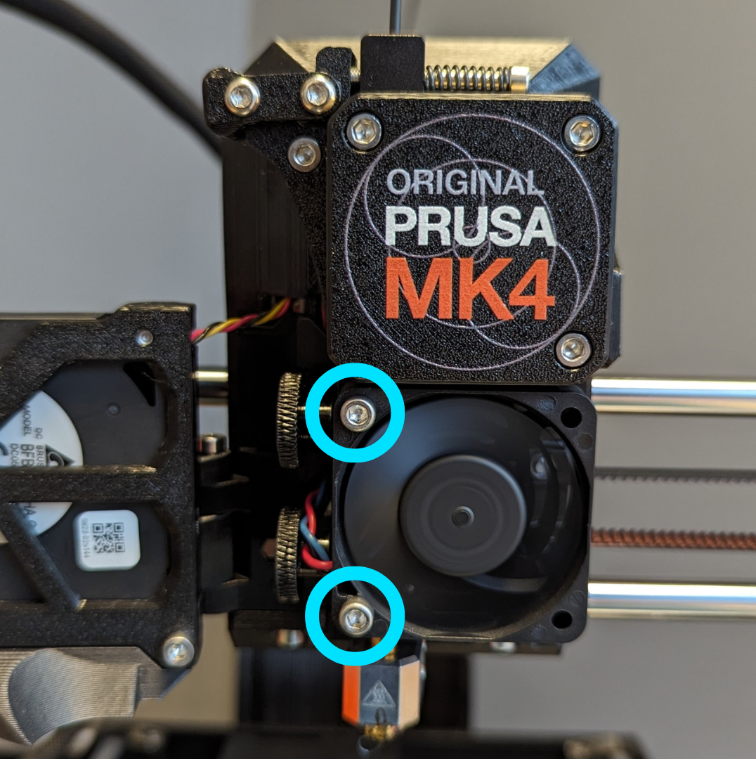
- Remove the 2 screws securing the print fan to the hotend assembly.
-
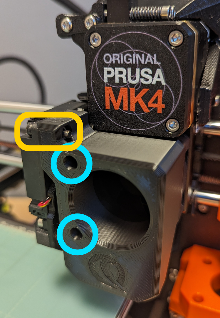
Slot these screws through the holes on the front of the hotend guard (P29) and screw them back through the print fan into the hotend assembly.
-
Close the part fan door against the hotend ram (P29).
-
Using the provided M3x15 screw and M3 hex nut, slot the nut into the slot on the top of the hotend guard (P29) and secure the part fan door to the hotend guard (P29).
3.5 Install Front Ramp
- Remove the spring steel sheet from the heatbed, and unscrew the nine torx screws securing the heatbed to the Y-carriage.
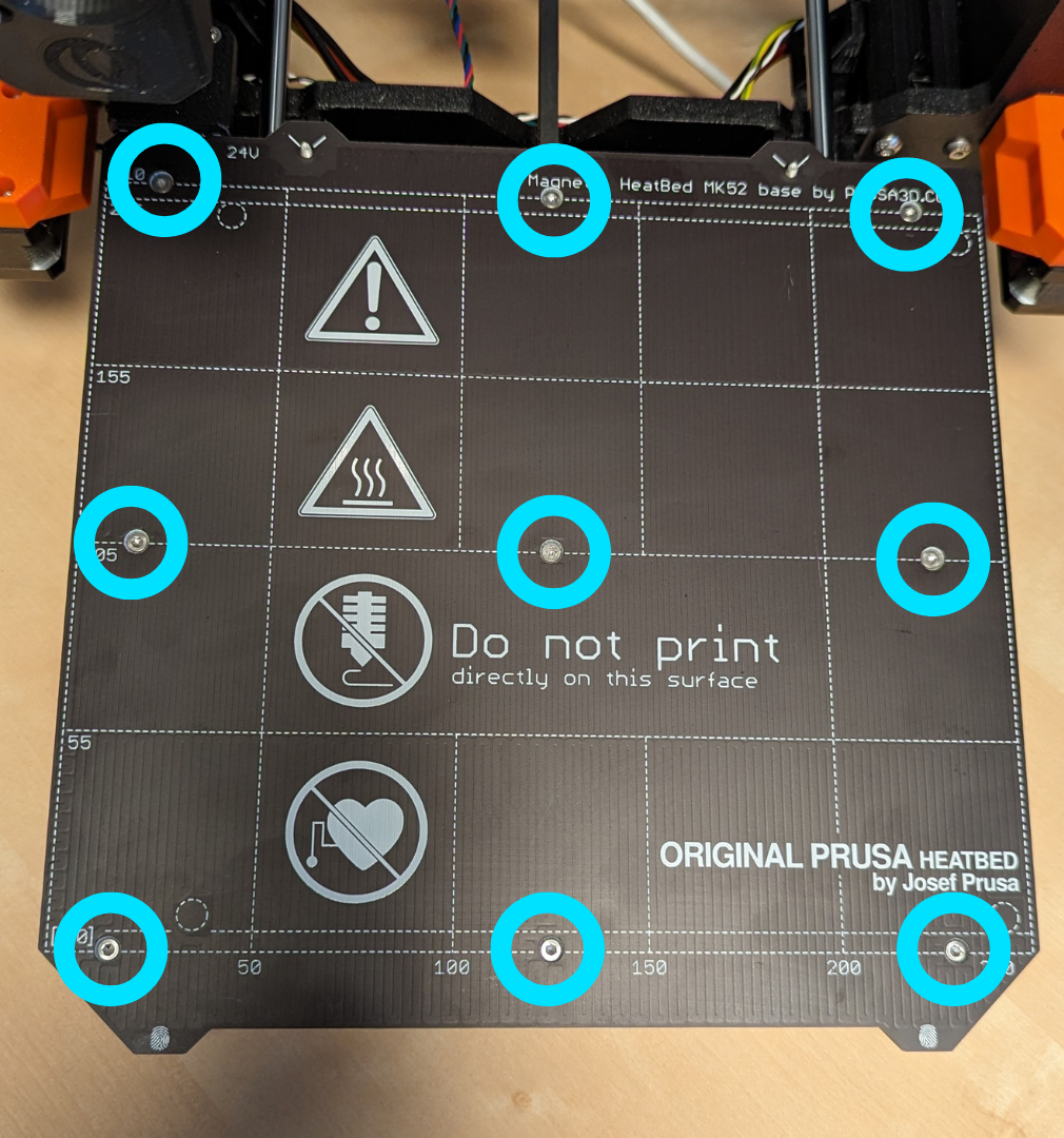
- Carefully lift the heatbed and set aside.
There is a spacer under the center torx screw that will be loose upon removing the screw, be careful not to lose it!
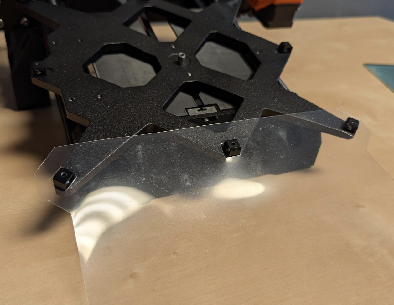
- Slot the holes of the provided plastic sheet over the front three Y-carriage spacers, as shown below. The curve of the sheet should scoop upward.
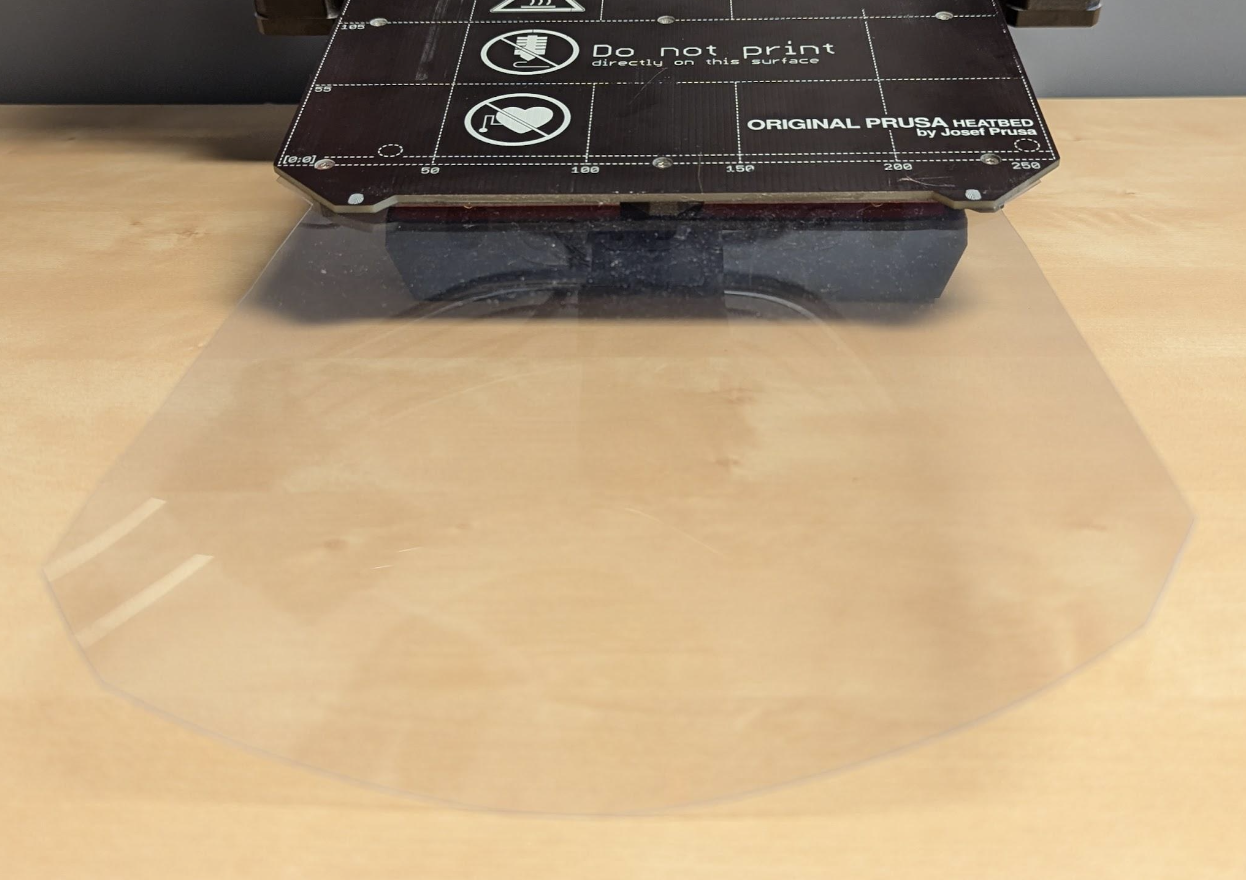
- Follow Prusa's installation guide to re-install the heat bed with the plastic sheet now sandwiched between the heatbed and the Y-carriage.
Uneven tightening of the heatbed screws can cause the bed to warp slightly, resulting in inconsistent bed-levelling.
If the purge line is coming out too squished, you may need to add a couple layers of packing tape to the front left corner of the heat bed to raise this portion of the print area slightly.
3.6 Install Bed Flexor
-
Prepare the bed flexor (P30) by installing the M5x8mm screw and 3030 T-nut.
-
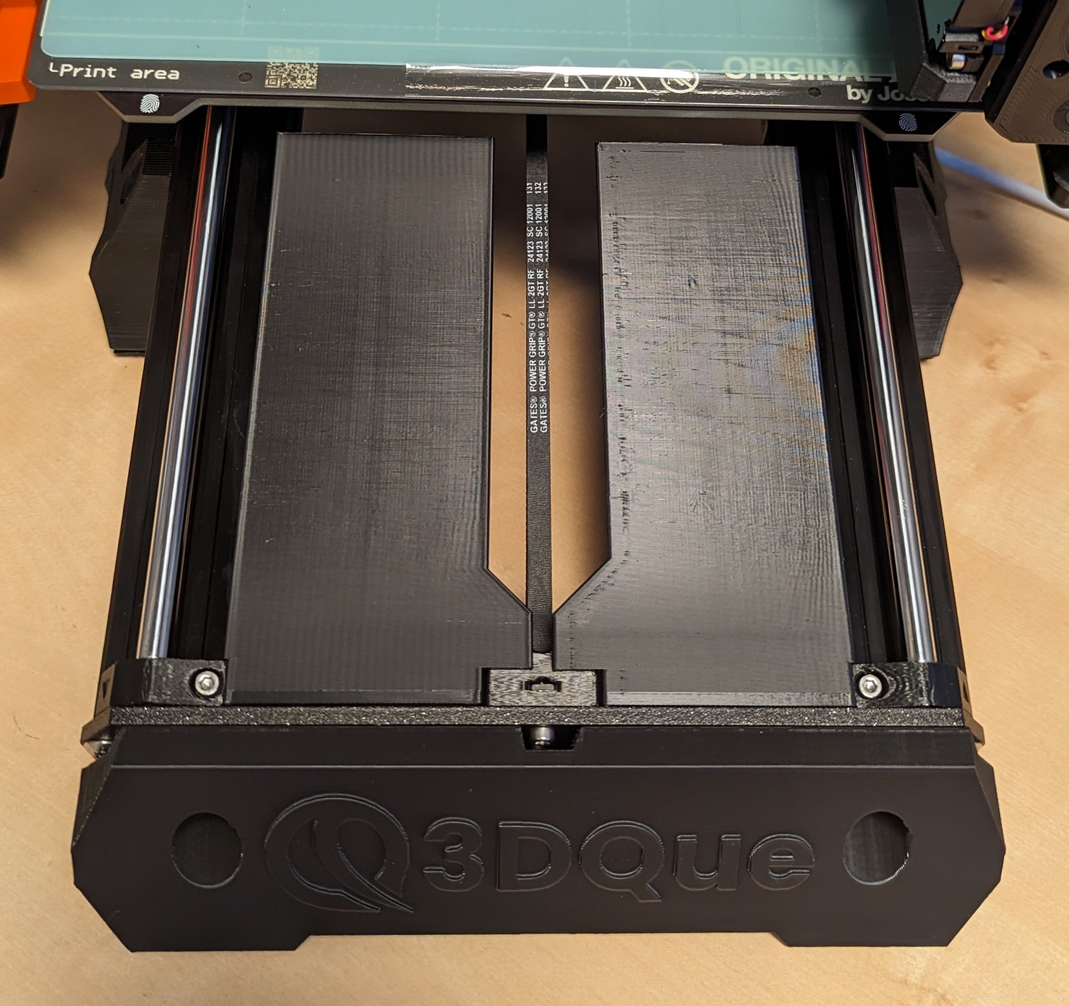
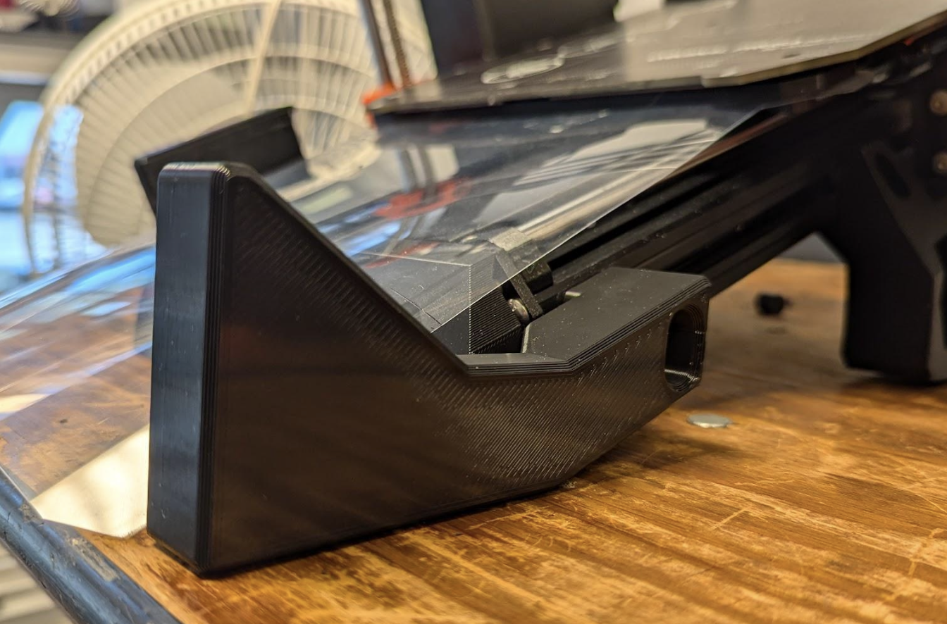
Using the bed flexor (P30), slide the T-nut into the right side of the printer frame.
-
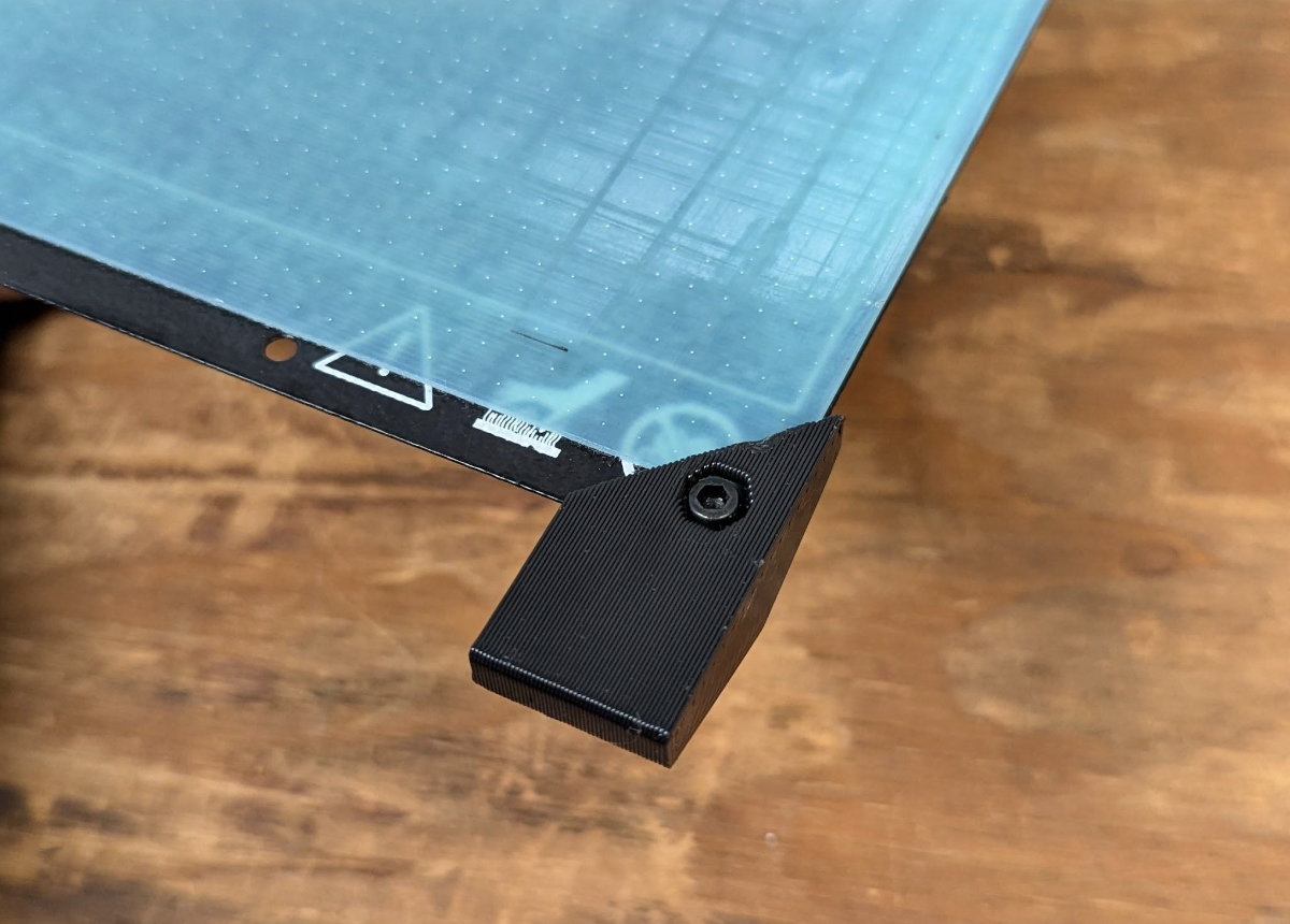
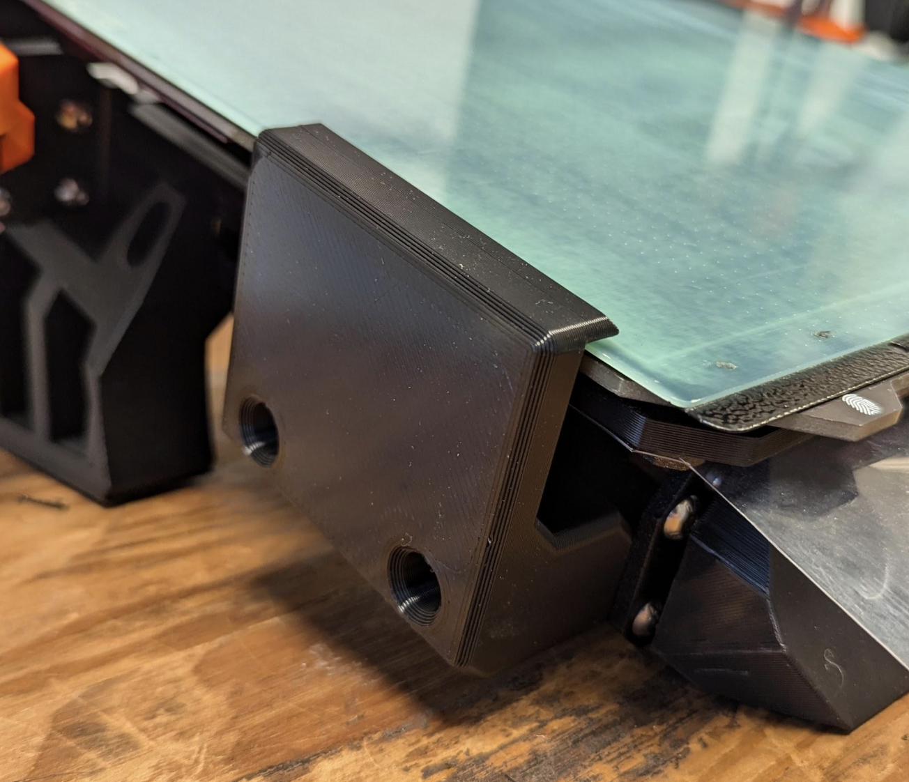
With the T-nut in the frame, slide the bed flexor forward until its bottom edge rests flush against the table surface, as shown below.
-
Tighten the bolt/T-nut.
- Slide the corner attachment (P31) over the front right corner of the spring steel sheet.
-
Using the attachment as a guide, drill a ~3.5mm diameter hole through the spring steel sheet.
-
Using the provided M5x8mm cap screw and M3 hex nut, secure the corner attachment to the corner of the spring steel sheet.
-
Prepare the bed guide (P32) by installing the M5x12mm screws and 3030 T-nuts.
-
Using the bed guide (P32), slide the T-nuts into the left side of the printer frame.
-
With the T-nuts in the frame, slide the bed guide all the way forward and tighten the bolts/T-nuts.
All done!
Before starting any prints, be sure to re-run all calibration wizards to compensate for any parts that may have been affected by the kit installation.