CR10 [V1-V3] and CR10S
Compatibility information
1.0 What's in the Kit
Tilt Frame
- 2 x Aluminum extrusion bases
- 4 x Rubber Feet
Printed Parts
- 1 x Tilt Bracket Left (C1)
- 1 x Tilt Bracket Right (C2)
- 1 x Inner Ramp Left (C3)
- 1 x Inner Ramp Right (C4)
Hardware
- 9 x M5x8mm Button Head Cap Screws
- 4 x M5 3030 T-nuts
- 6 x M5 2020 T-nuts
- 2 x M4 2020 T-nuts
- 2 x M4x8mm Socket Head Cap Screws
2.0 What You'll Need
- Allen Keys
3.0 Install Tilt Kit
-
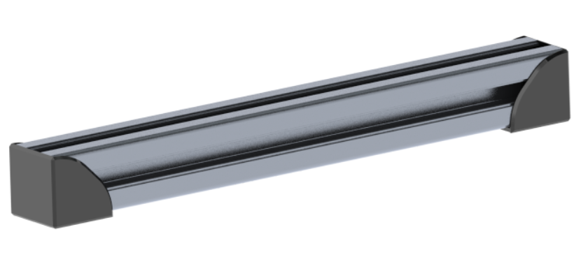
Attach the feet mounts (Q7) onto the ends of the provided aluminum extrusions, if not attached already, and ensure the top face of the extrusion is completely exposed.
-
Using the large T-nuts and M5x8mm bolts, attach the larger sides of the angle brackets (E17/E18) to the provided extrusion to make the base:
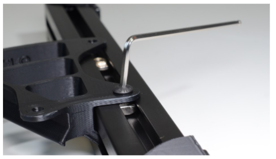
- Tilt in the taller edge to the extrusion and fasten with an M5x8mm bolt and large T-nut. The T-nut should rotate perpendicular to the slot as the bolt is fastened.
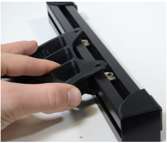
- Repeat mirrored bracket.
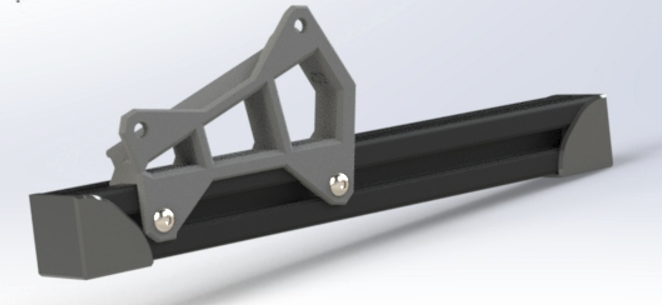
- Slide both brackets all the way to the end, just touching the feet mounts (Q7), as shown below
-
Assemble tilt base to the printer:
- Rotate the printer and lay it on its right side.
Install left inner panel (C3)
- Using the built-in clips of the panel, push the clip into the aluminum extrusion channel.
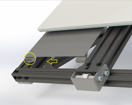
Attach the tilt bracket to the printer
- Place a small T-nut just behind the front rubber pad in the bottom slot
- Tilt in the bracket (narrow side forward) where it touches the front rubber pad
- Align the t-nut with the allen key, then fasten with an M5x8mm bolt
- Fasten a nut in the rear hole