Ender 3/Pro/V2
1.0 What's in the Kit
Printed Parts
- 5 x Part guidance ramps (E3, E4, E5, E6, E7)
- Center Ramp (E3)*
- Front Ramp Left (E4)
- Front Ramp Right (E5)
- Side Ramp Left (E6)
- Side Ramp Right (E7) 1 x Angle Bracket Left (E17) 1 x Angle Bracket Right (E18) 1 x Spool Holder Angle Bracket (E8) 1 x Front Foot (E15) 1 x LCD Mount Bracket (E16)
Hardware
- 6 x M5 Small T-nuts
- 6 x M5 x 8mm Screws (1 spare)
- 2 x M5 x 25mm Screws
- 4 x M5 Hex Nuts
- 4 x Rubber Feet
2.0 What You'll Need
- Allen Keys
3.0 Install Tilt Kit
-
Remove LCD and spool holder, keep screws and nuts.
-
Prepare the E17 and E18 tilt brackets by installing the M5x8mm and 2020 T-nuts to prepare them for the printer.
-
Using the provided rubber feet, peel off and adhere to the bottom of the tilt brackets (E17/E18), front foot (E15), and LCD mount (E16) using the provided slots.
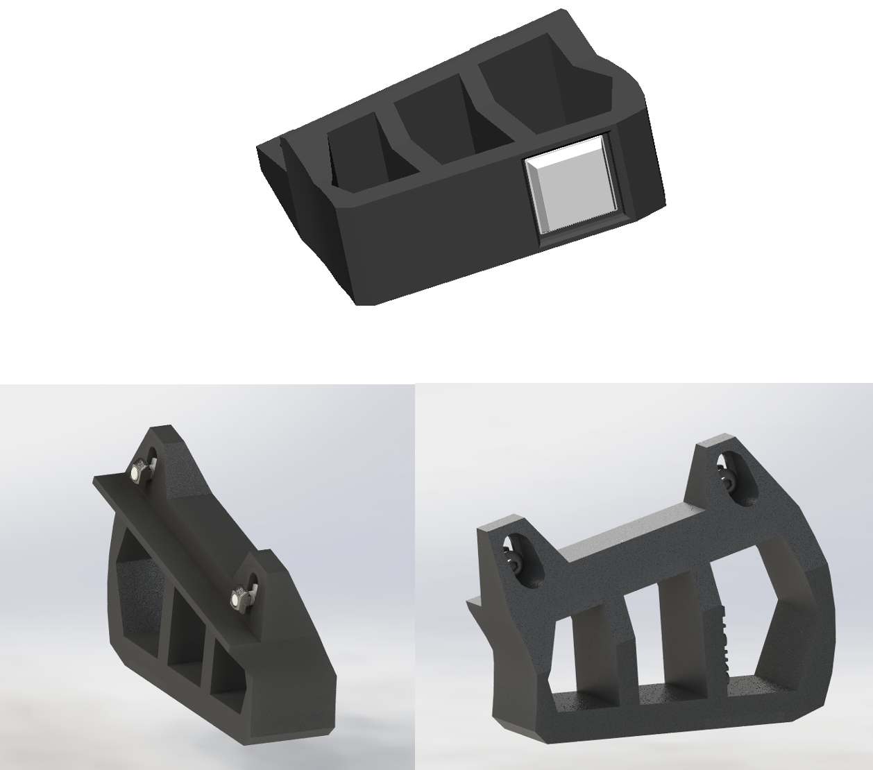
-
On a clean a table, gently rotate your Ender 3 onto its left side.
-
Slide in the T-nuts of the E18 tilt brackets and slide the tilt brackets until the front of the tilt bracket is 115m from the front of the printer. Tighten the fasteners.
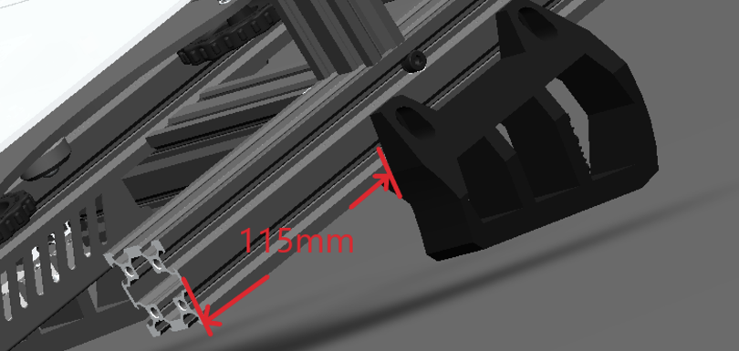
-
Rotate the printer on its right side and repeat step 5 for E17 tilt bracket.
For Ender 3 V2: Skip to step 12.
-
Unscrew M5 screws fastening the electronics box from the front, see below.
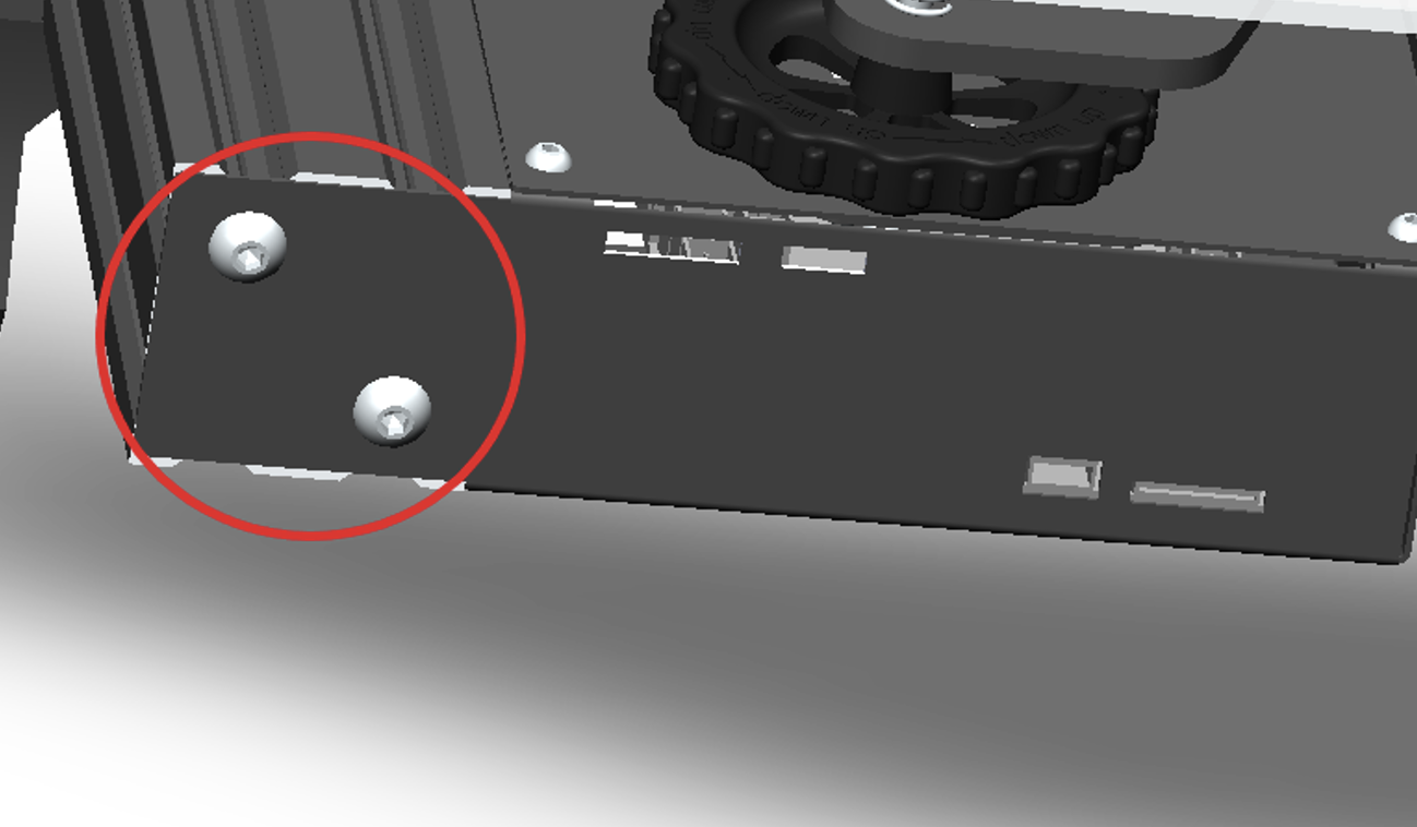
-
With the E15 front foot, use the provided M5x25mm screws to fasten the E15 to the printer. Keep screws loose for now as there will be a need for space for E4 front ramp later.
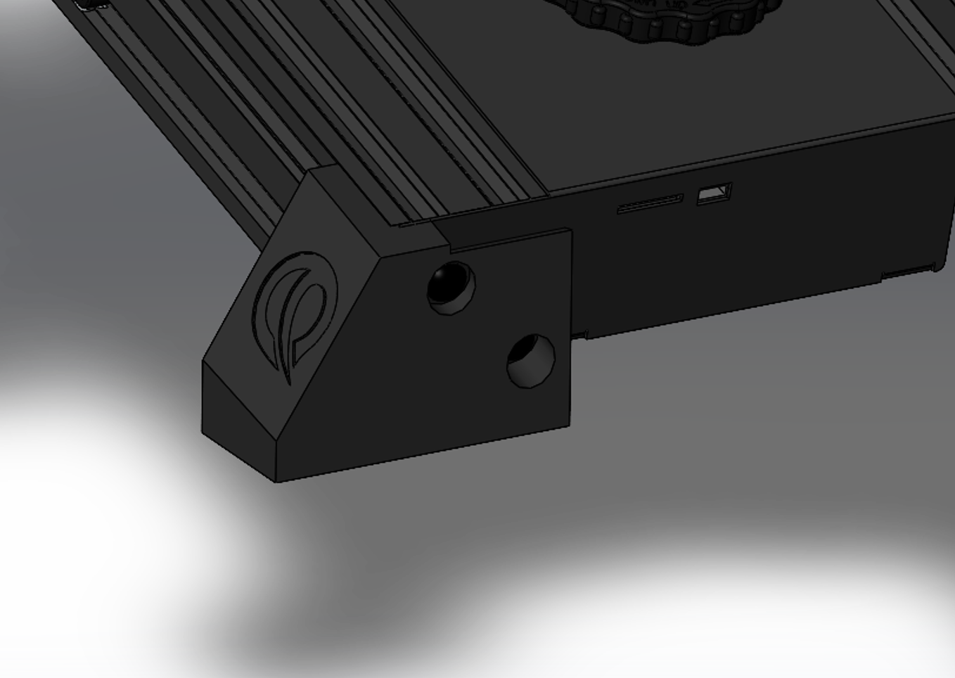
-
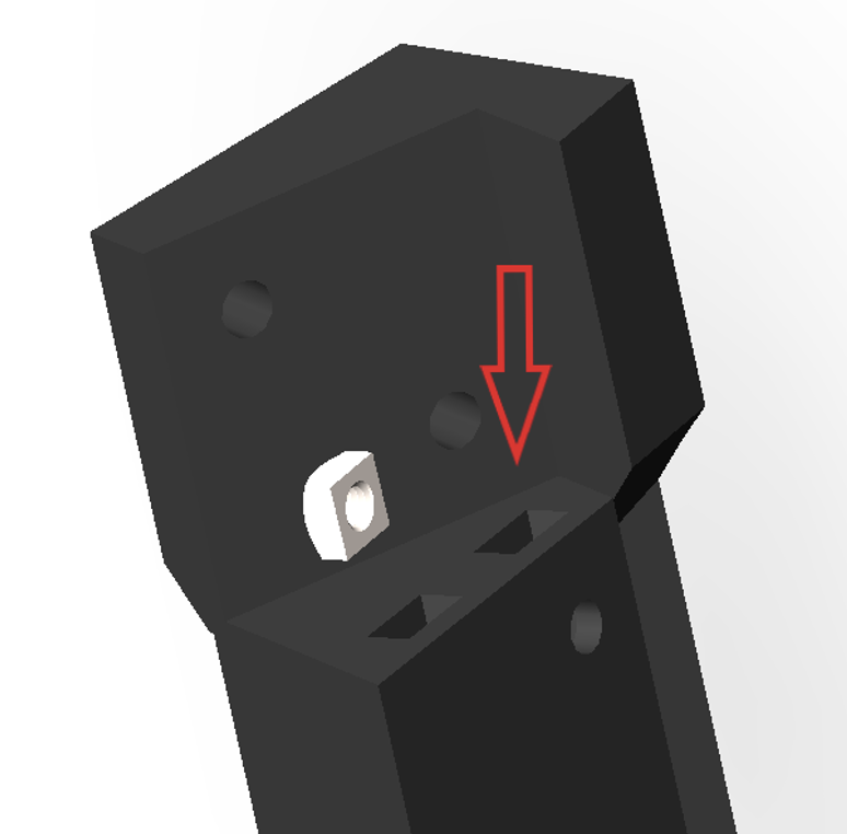
With the E16 LCD Mount, insert the 2 square nuts provided into the holes on the aft side of the mount.
-
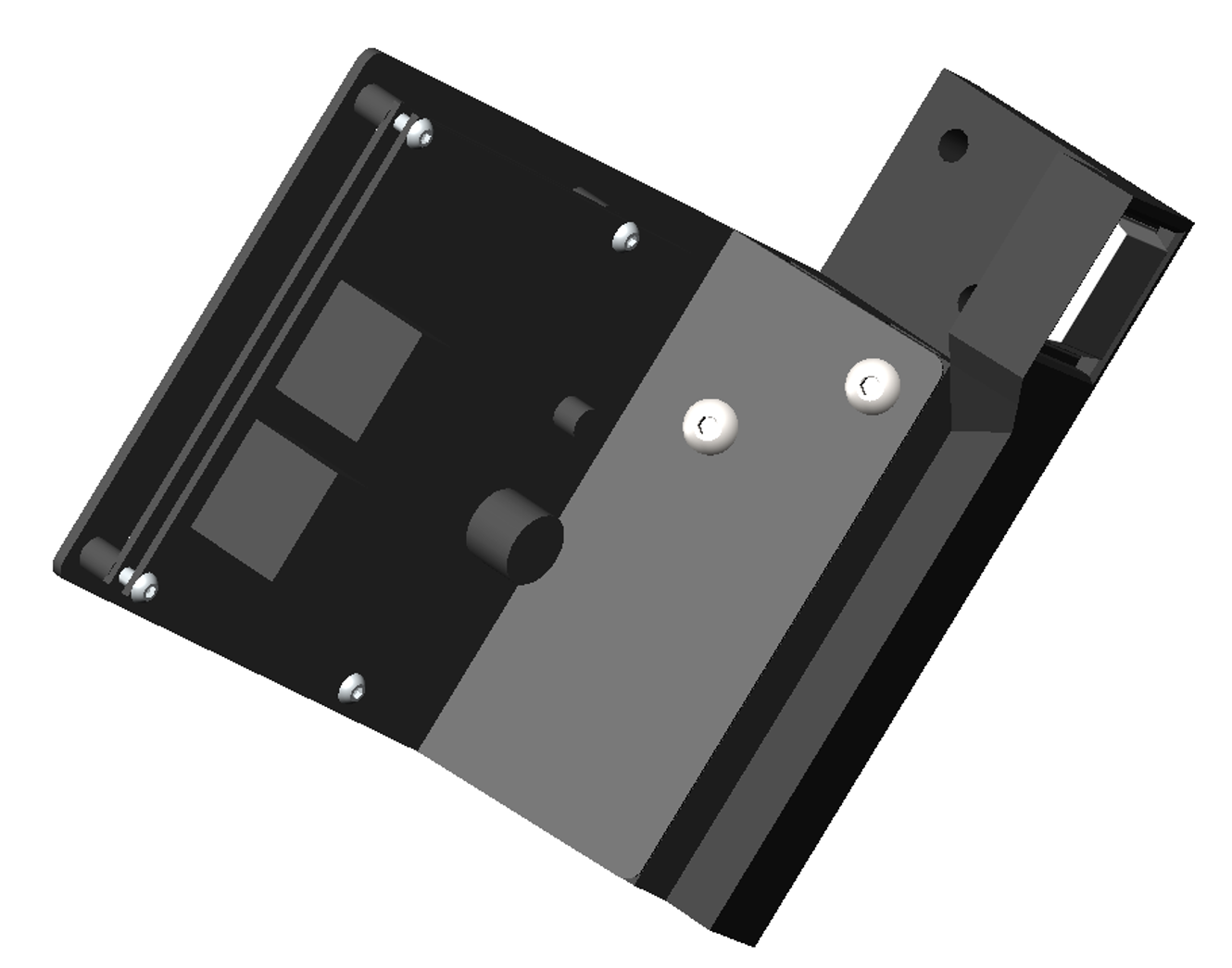
Align the holes of the LCD plate with the holes of the LCD mount and fasten using the provided M5x8mm.
-
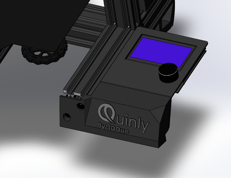
Similar to the front foot, using the provided M5x25mm screws, fasten the LCD mount.
-
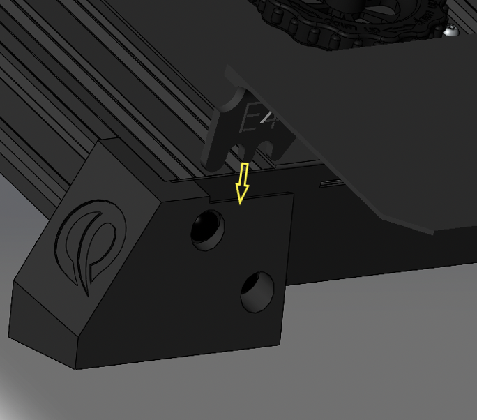
Using the E4 left front ramp, slide the flange into the gap as shown below.
-
Clip the other end of E4 into the bottom slot of the extrusion as shown.
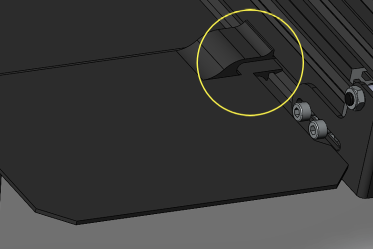
-
Using E5 right front ramp, slide in E5 flange into the gap as shown below.
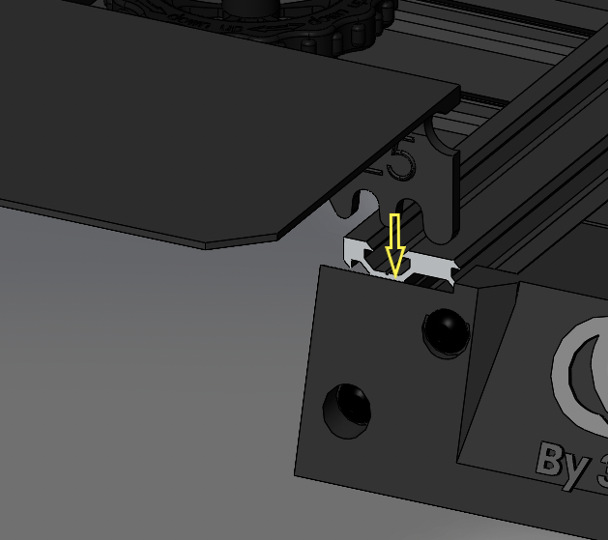
-
Clip the other end of the E5 into the appropriate slot of the extrusion as shown.
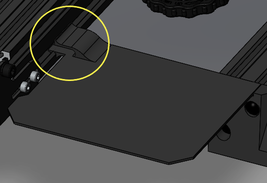
Depending on the version of Ender 3 that you have, there may be a gap present on both E15 and E16. This is acceptable.
-
Using E3 center ramp, clip into the slot as shown.
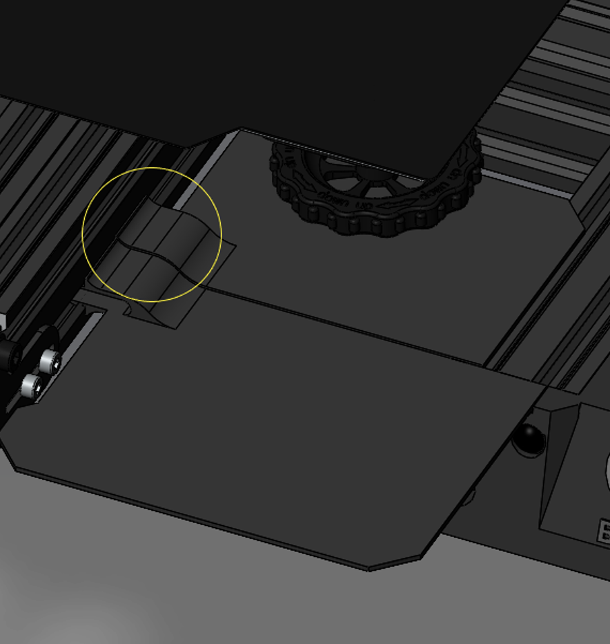
-
Clip on the E6 and E7 Side ramps on the side extrusions.
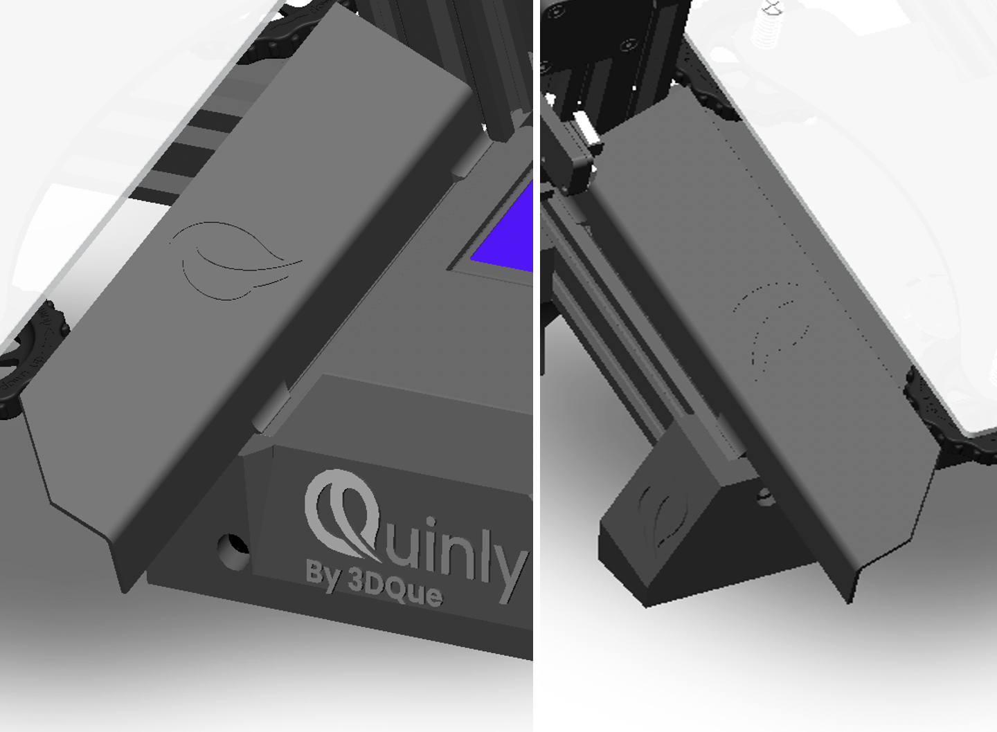
(For a stock Ender 3 Install the Spool Holder Adapter, follow instructions below. Otherwise, done!)
-
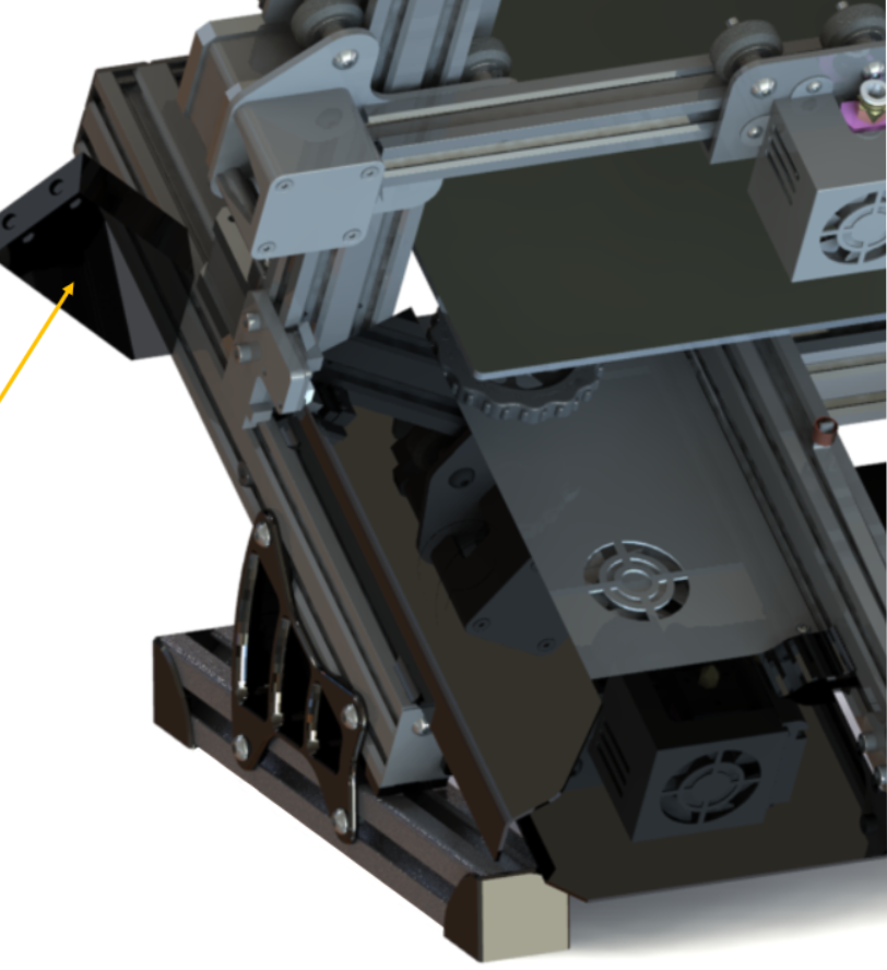
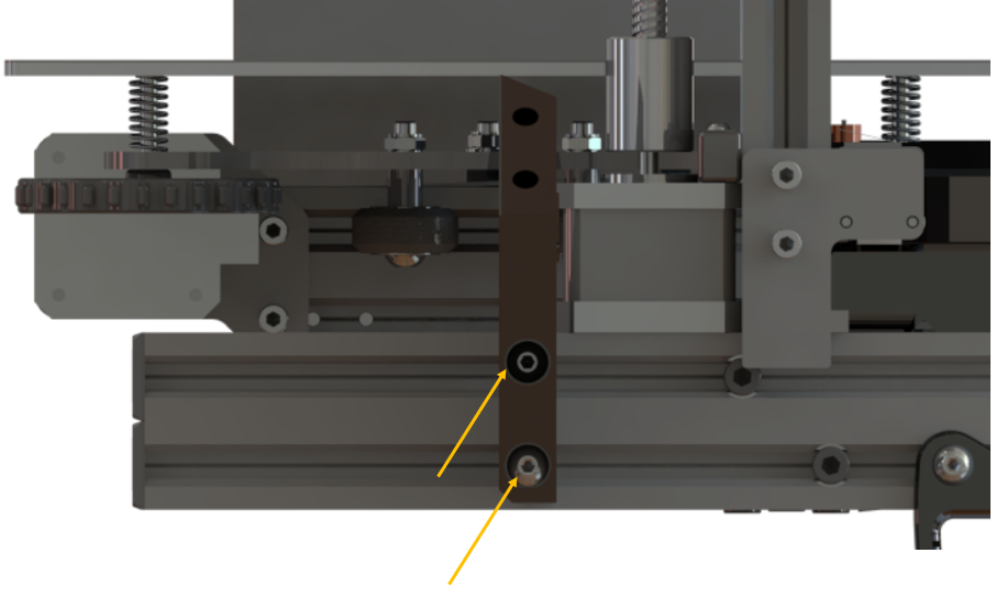
Using M5 x 25 cap screws and T-nuts removed earlier, install the spool holder adapter vertically on the left hand side of the printer frame, as shown.
-
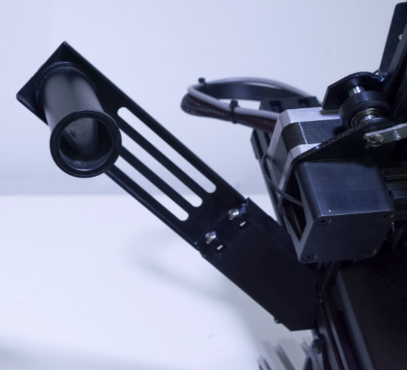
Attach the original spool holder to the adapter using the nuts and T-nuts that were put aside during removal. Ensure that the flat side of the metal bracket is facing backwards, as pictured.
-
Alternate spool mounting prints are available on the resources page i.e. for use with a direct drive system.
Done!